Multimeters can give false voltage readings if they have a low battery even without the low battery warning.
I mounted the components for the voltage regulator for the MOSFET Driver Board in order to test the regulator by itself. The regulator drops the voltage from the 48V solenoid power supply to between 1.2V to 30V. The 30V upper limit was set because the D223 optocouplers cannot handle more than 30V so it is pretty important that this works.
The regulator pot was used to set the voltage output to 12V but the 12V started to drift high, just tenths of a volt at a time. I thought that my regulator just needed to come to steady state as my set resistors were heating up and thereby causing the voltage to drift. Also, the 48V power supply is one of those cheap ones off eBay or Amazon so I did not trust it very much. After a few minutes, the voltage was still going up and I tested the voltage supply and it was up to 56V. This output was well within the realm of possibility as there was some adjustment on the power supply. Enter the Canadian Tire special, Motomaster Multimeter, my backup multimeter that I had not taken out in a long time. Again, too high voltage but then my nicer multimeter, a Brymen 829, starts beeping saying it has an internal error.
Turns out the 9V battery for the Brymen was nearly flat and did not have enough voltage so this likely caused it to lose its voltage reference. My backup multimeter just happened to be experiencing the same problem as I had not taken it out in a long while and the battery had also not quite died. I had not experienced this before because normally the Brymen's battery lasts for ages and I often accidentally leave my Motomaster one on so the battery never gets a chance to run flat.
It is actually fairly rare for this scenario to occur as batteries lose their voltage drastically near the end of their life (See the chart below). So to have two multimeters whose batteries were in that region at the same time is pretty unlucky. Good to know my power supply is not fried.
Update: Replaced the batteries and both multimeters are reading fine. The Brymen's battery had dropped to 7V and the Motomaster to 5.5V. Honestly, I am a little surprised that the Brymen lost its voltage reference at only 7V. Maybe for the Brymen this was a case of a lose connection to the battery.
I mounted the components for the voltage regulator for the MOSFET Driver Board in order to test the regulator by itself. The regulator drops the voltage from the 48V solenoid power supply to between 1.2V to 30V. The 30V upper limit was set because the D223 optocouplers cannot handle more than 30V so it is pretty important that this works.
 |
| MOSFET Driver Board with Linear Regulator Mounted |
The regulator pot was used to set the voltage output to 12V but the 12V started to drift high, just tenths of a volt at a time. I thought that my regulator just needed to come to steady state as my set resistors were heating up and thereby causing the voltage to drift. Also, the 48V power supply is one of those cheap ones off eBay or Amazon so I did not trust it very much. After a few minutes, the voltage was still going up and I tested the voltage supply and it was up to 56V. This output was well within the realm of possibility as there was some adjustment on the power supply. Enter the Canadian Tire special, Motomaster Multimeter, my backup multimeter that I had not taken out in a long time. Again, too high voltage but then my nicer multimeter, a Brymen 829, starts beeping saying it has an internal error.
Turns out the 9V battery for the Brymen was nearly flat and did not have enough voltage so this likely caused it to lose its voltage reference. My backup multimeter just happened to be experiencing the same problem as I had not taken it out in a long while and the battery had also not quite died. I had not experienced this before because normally the Brymen's battery lasts for ages and I often accidentally leave my Motomaster one on so the battery never gets a chance to run flat.
It is actually fairly rare for this scenario to occur as batteries lose their voltage drastically near the end of their life (See the chart below). So to have two multimeters whose batteries were in that region at the same time is pretty unlucky. Good to know my power supply is not fried.
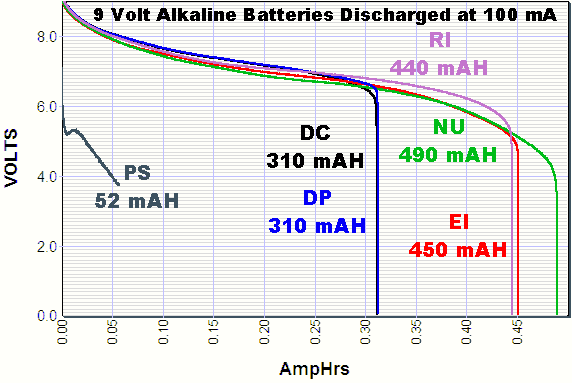 |
| 9V Discharge Curve via Powerstream.com |
Comments
Post a Comment