
ATX Breakout Board

Last November, I fried my 'lab power supply' that I made from a computer PSU.  I was testing my solenoids and the stress was just too much for the PSU.  The mistake I made was rapidly turning on and off my solenoid which likely resulted in voltage transients (spikes).  Since the PSU does have a current limiter, it was likely the constant voltage spikes that caused the damage.  There are various methods to suppress voltage transients such as by-pass capacitors and zener diodes.  In particular solenoids and other inductive loads experience these voltage spikes, hence my no longer functioning bench power supply.

ATX Breakout Board
I could have just rebuilt the same power supply by adding binding posts etc to the PSU housing but after searching the internet an ATX power supply breakout board seemed a popular option.  The main advantage compared to my old power supply was the addition of fuses on the outputs.  The extra safety this provides is perfect for bench top testing of circuits.

Since I have not touched electronics for a long time, I though that this was a good opportunity to relearn how to design a PCB with EagleCAD.  I essentially copied the ATX breakout boards from Dangerous Prototypes (via Seeedstudio) and Sparkfun.

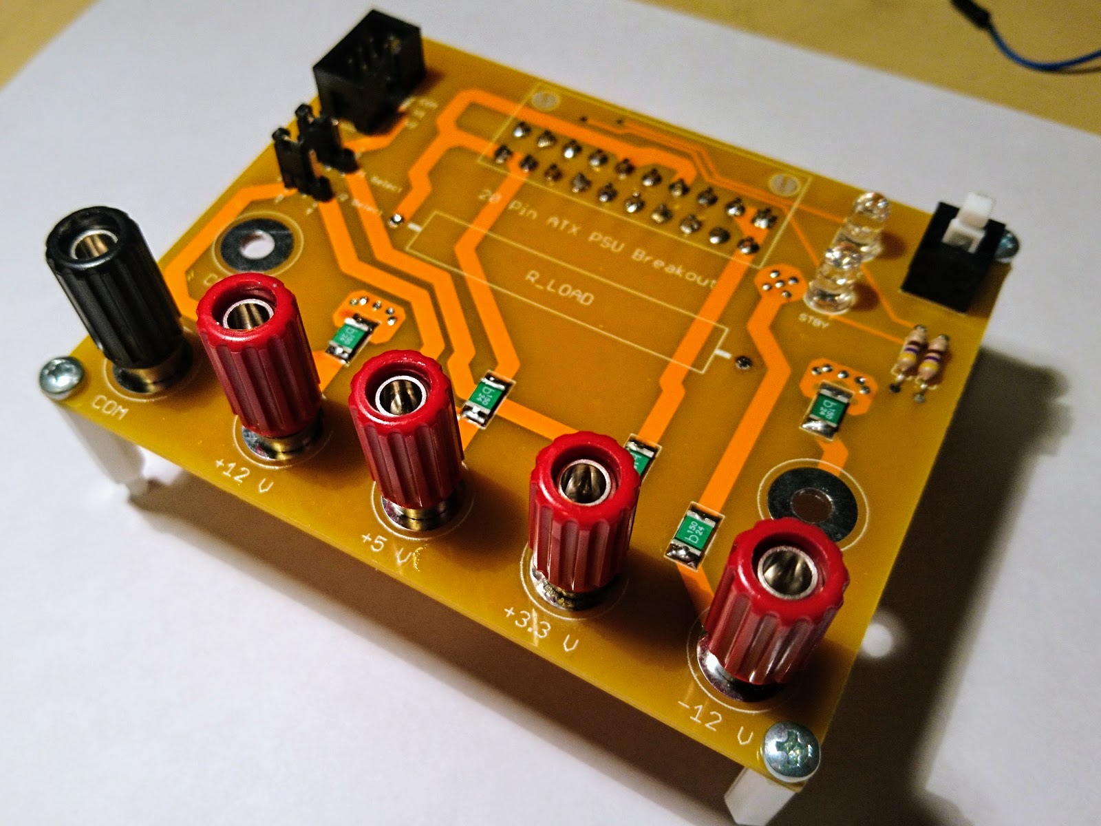
The circuit is very simple.  You have to short PS_ON pin to ground in order to turn on the power supply.  The +5VSB (Standby) and PWR_OK pins can be used to add indicator LEDs.  There is a place for a load resistor which is sometimes needed on the 5V in order to turn on the PSU.  However, this was not required for my PSU.  I also added in a 6-pin header for a ribbon cable with selectors for the voltage to make an easy plugin for a breadboard.

Despite the simplicity, I made a pretty bad error.  In the photo above, you can see that the ATX header is solder in on the bottom of the board.  I set the pinout for the header per the pinout below which is the pinout as viewed from the male connector.  It should actually be the mirror image because the header is the female connector.  Luckily I was able to rectify the issue by soldering the header to the bottom of the board.  A corrected schematic and PCB layout can be seen below.
ATX 20-Pin Pinout from Male-Connector via Wikipedia

ATX Breakout Schematic

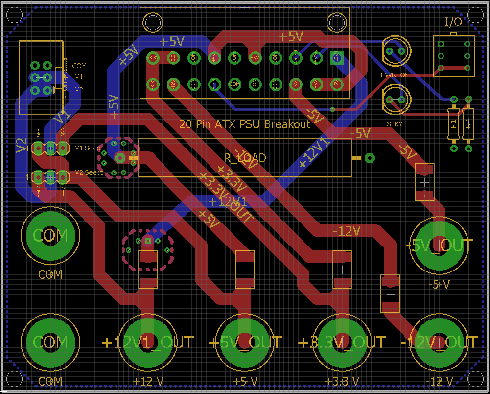
ATX Breakout PCB Layout
Note the additional vias where the +12V and +5V traces change layers.  These are to ensure better connectivity and current capacity between the layers.  I learned this layout technique from examining the Dangerous Prototypes ATX breakout board.

This was a fun simple project that helped me get back into electronics and relearn how to use EagleCAD.  My advice though would be to just purchase the Dangerous Prototypes version as it has the same surface mount resettable PTC fuses.  If you need the rails limited to a higher amperage, go for the Sparkfun setup as it is difficult to find cheap PTC fuses greater than 1.25A.  Worse case, you can just jumper the fuses.


Comments

Popular posts from this blog

Pinball Cabinet Beginnings

I was getting to the point where I really needed to build on something. I have numerous pinball parts but have nothing to attach them to. I managed to find some pinball plans for a Williams Widebody pinball machine. All the measurements are in mm sadly even though all pinball cabinets are in inches. I converted and change it all to the nearest quarter inch. Well sort of. The guy who measured this was intending on using 45 deg cuts in the corners. My skill saw is too cheap for that so I changed the measurements for butted joints. The interior is set for a 23.5" wide playfield. The length of the cabinet is 51.5" in total. I used 3/4 inch plywood so the bottom would be 50" long for example. You can pretty much dimension the rest from there.  I did get a little chipping of the plywood but I went out and bought a blade with more teeth for finer cuts. It's a 60 tooth saw blade and my skill saw doesn't really have enough power for it so I have

MOSFET Driver Board

Final version?  I hope so.  I have gone back and redesigned my solenoid driver board several times.  In previous versions I attempted to offload some of the logic from the microcontroller.  For example, I used a Schmitt-Trigger [74HC14] with an RC network to provide a single pulse to the solenoid.  Also, I added in a PWM signal to set the average voltage 'seen' by the solenoid.  This worked but was very limiting to have the pulse length hardwired in and it was difficult to adjust without more expensive precision potentiometers. I chose to simplify my circuit to make it a general MOSFET driver for flexibility.  Since I have more than enough space inside my pinball cabinet, it was not a problem to have the extra boards.  The boards were designed to have 4-channels since by default I would get a minimum of 10 boards for the same price from Seedstudio.  Also, the cheapest board option was restricted to 10cm x 10cm otherwise the price balloons quickly. Driving 48V from a separa

Pinball Solenoid Control

Pinball solenoids come with designations like 23-800.  The first number, 23 in this case, represents the American Wire Gauge (AWG) used.  The second number, and the more important number, is the number of windings which is related to its power rating.  A solenoid with less windings, say 400, is more power and is used for such applications as actuating the flippers.  These solenoids get very hot very quickly, which increases the resistance of the solenoid thereby decreasing the current and therefore the power.  To avoid overheating, these high powered solenoids will have two coils.  One for the main actuation of the solenoid, and another to maintain the position.  The second solenoid will have a smaller wire gauge and more windings.  In example, my flipper 'coils' are 15-411, 15 AWG and 411 windings.  They are quite strong and found in some of the latter Williams pinball machines such as the popular Adams Family machine.   You can find a lot of good additional information